Baldy201
New Member
As seen on Team-Integra.net
I. HEADER DESIGN
For specific information on various header brands for the Bseries, please go to this link of my other header article at:
http://www.hondavision.com/showthread.php?s=&threadid=4971
It is bandwidth intensive with many jpeg's and so please be patient and allow it load if you have a 56k modem.
The most common thing you hear is 4-2-1 makes more midrange power at the sacrifice of peak hp and 4-1 makes more peak power at the sacrifice of midrange power.
Is this always true?
Not these days, when we have long hybrid 4-2-1's which combine the extra length of a traditional 4-1 and the layout of a traditional 4-2-1 (or tri-Y as they are sometimes called) into one header. Why is this new and different?
The header's primary tubes, secondary tubes, and collectors length & diameter affect WHERE power is created along the rpm range.
To understand how header design affects power and powerband location, you have to first understand how the ACTUAL or REAL torque curve is shaped relative to the IDEAL shape of the torque curve when there is maximal cylinder filling, as shown in the graph here below:

Explanation of the above graph:
Exhaust gas flow velocity (or flow speed) determines where peak torque occurs along the rpm range. As a general rule, when exhaust flow velocity reaches the mean value of 240-260 ft/sec., peak torque is achieved.
Peak torque also marks when your engine has achieved it's highest volumetric efficiency (or maximal cylinder filling ability). Control how fast you can get up to a mean flow velocity of 240-260 ft/sec by looking for certain header-exhaust characteristics or design and you control WHERE peak torque occurs.
Notice that even if you can get optimal cylinder filling to achieve optimal volumetric efficiency, other factors, like how much exhaust gas you can remove from the cylinder after combustion, affects the maximal "actual" torque you can squeeze out of your engine package.
------------------------------------------------
GOALS OF AN ENTIRE EXHAUST SYSTEM
The 2 goals of a header-cat-exhaust system is to:
a) to efficiently remove as much of the combusted inert exhaust gases out of the cylinder.
Remember that burnt exhaust gas is inert or does not combust twice (EGR & fuel economy is another story) and therefore cannot make power, if it is still left in the cylinder...it takes up space in the cylinder and prevents fresh air and fuel from coming into the combustion chamber to make power.
b) to keep the velocity or speed of the exhaust gas leaving very high.
When high exhaust gas speeds are reached, a wake is created from an exhaust pulse leaving the cylinder head (see SurferX's exhaust article here for some nice pics of this wake or pulse). Following behind this wake is a low pressure wave that acts like a vacuum. This vacuum sucks in more fresh air and fuel at cam overlap, when the intake valve is just starting to open and the exhaust valve is almost about to close. Since both the intake & exhaust valves are partially open at this time of cam overlap, header is actually "connected" to the intake manifold & intake port for a brief period. The exiting exhaust gas helps pull in the next fresh intake air & fuel. This is called scavenging. And scavenging is what helps draw in more oxygen and fuel for combustion.
More fresh air and fuel coming in, with less inert burnt exhaust gases occupying combustion chamber volume, makes more power.
----------------------------------
A. FIVE HEADER DESIGN FACTORS AFFECTING WHERE PEAK TORQUE OCCURS
There are several aspects of header and exhaust tubing that affect when a mean exhaust flow velocity of 240 ft/sec. is achieved:
1. Diameter (or header tube cross-sectional area) :
Bigger diameter shifts peak torque to a higher rpm compared to a smaller diameter.
The bigger the diameter, the more cross-sectional area. Exhaust flow must overcome this extra tube cross-sectional area and therefore the flow travels slower . It takes the rpms to climb to a higher rpm before the speed of 240 ft/sec (and therefore, peak torque) is reached. So increasing diameter shifts when 240 ft/sec and peak torque is achieved to a higher or later rpm, because it takes longer for the air flow speed to reach 240 ft/sec.
In addition, a bigger diameter will increase the actual peak torque number (i.e. not only does diameter change the location, it also increases torque) .
You can also vary diameter, as well, along the length of the header tube: This is called "stepping" the header. A "stepped" header will have along it's length the diameters gradually increasing as it moves towards the muffler end and away from the engine. Stepping a header will prevent exhaust flow from travelling backwards to the engine (called reversion). Stepped headers therefore have anti-reversion characteristics, as well as achieving a broader powerband.
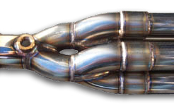
Figure 1. Here is a pic of stepped diameters on a Toda header where the diameters start at 45mm near the flange, then gradually increases to 50 mm further down at the secondaries, and 60mm just before the collector. Several good aftermarket headers are stepped.
Some people port the JDM ITR or DC JDM 4-1 flange ports to a little larger diameter than the cylinder head exhaust port diameter to get this stepped effect early. Some people also port the JDM ITR 4-1 collector. Here's how much to dremel port the JDM ITR flange ports:
quote:
--------------------------------------------------------------------------------
from Dave Stadulis at SMSP
you don't want to have the exhaust port on the head exactly matched to
the manifold/header...I've been told to have the header port about 1mm
(.039") larger all around the head port and no larger than 1/16". This
provides an anti-reversion attribute to the header. The same goes for
steps in the individual tubes.
--------------------------------------------------------------------------------
2. Length:
Longer tubes will create more torque at the rpms before peak torque.
How do they do this?
Longer tubes will speed up air flow velocity. The flow velocity of 240 ft/sec and peak torque will occur at an earlier rpm compared to a shorter tube. Changing the length of the header primary tubes does not increase the value of peak torque like diameter does. Instead length changes the behaviour of the torque around peak torque along the rpm band.
If you imagine the torque vs rpm curve from a dyno to be like a see-saw: then, on a see-saw there is a point where the plank sits to allow it to rock up and down. This is usually in the middle of the see saw and is also called the fulcrum. On our torque vs rpm curve, imagine the peak torque to be the fulcrum, although this fulcrum doesn't necessarily have to be in the middle like the see-saw...it can be moved. Changing length "rocks" the torque curve about the peak torque.
If you have a longer primary header tube, the torque curve will "rock" in such a way that the left side is higher than the right side. There is higher torque at earlier rpms before peak torque. There is less torque at later rpms after peak torque.
If you shorten the length of the primary tube, the torque curve will will have the see-saw with the right side higher than the left. So there is more torque at later rpms after peak torque.
3. Merge Collector Diameter, Length, Angle, and Layout:
In terms of header layout, merge collectors are the portions of the header where the tubes join.
So in a 4-2-1 header, the 4 primary tubes are first joined at a collector into 2 tubes. The 2 tubes are then joined by a second collector into 1 tube.
In a 4-1, the 4 primaries are joined at only 1 collector into 1 tube.
In some cases, the collectors are in a box shape where 2 tubes are stacked directly on top of the other 2 tubes. In other cases, the collectors have the top 2 tubes offset from the bottom 2 tubes. This is called a tri-Y collector. The box collectors give less header ground clearance than tri-Y collectors.
Hytech Tri-Y collector
Hytech Box Collector
The collectors join the tubes and co-ordinate the 4 exhaust pulses leaving the primaries.
Shorter, large diameter collectors have more peak power.
Longer , smaller diameter collectors have more power in the midrange.
I. HEADER DESIGN
For specific information on various header brands for the Bseries, please go to this link of my other header article at:
http://www.hondavision.com/showthread.php?s=&threadid=4971
It is bandwidth intensive with many jpeg's and so please be patient and allow it load if you have a 56k modem.
The most common thing you hear is 4-2-1 makes more midrange power at the sacrifice of peak hp and 4-1 makes more peak power at the sacrifice of midrange power.
Is this always true?
Not these days, when we have long hybrid 4-2-1's which combine the extra length of a traditional 4-1 and the layout of a traditional 4-2-1 (or tri-Y as they are sometimes called) into one header. Why is this new and different?
The header's primary tubes, secondary tubes, and collectors length & diameter affect WHERE power is created along the rpm range.
To understand how header design affects power and powerband location, you have to first understand how the ACTUAL or REAL torque curve is shaped relative to the IDEAL shape of the torque curve when there is maximal cylinder filling, as shown in the graph here below:

Explanation of the above graph:
Exhaust gas flow velocity (or flow speed) determines where peak torque occurs along the rpm range. As a general rule, when exhaust flow velocity reaches the mean value of 240-260 ft/sec., peak torque is achieved.
Peak torque also marks when your engine has achieved it's highest volumetric efficiency (or maximal cylinder filling ability). Control how fast you can get up to a mean flow velocity of 240-260 ft/sec by looking for certain header-exhaust characteristics or design and you control WHERE peak torque occurs.
Notice that even if you can get optimal cylinder filling to achieve optimal volumetric efficiency, other factors, like how much exhaust gas you can remove from the cylinder after combustion, affects the maximal "actual" torque you can squeeze out of your engine package.
------------------------------------------------
GOALS OF AN ENTIRE EXHAUST SYSTEM
The 2 goals of a header-cat-exhaust system is to:
a) to efficiently remove as much of the combusted inert exhaust gases out of the cylinder.
Remember that burnt exhaust gas is inert or does not combust twice (EGR & fuel economy is another story) and therefore cannot make power, if it is still left in the cylinder...it takes up space in the cylinder and prevents fresh air and fuel from coming into the combustion chamber to make power.
b) to keep the velocity or speed of the exhaust gas leaving very high.
When high exhaust gas speeds are reached, a wake is created from an exhaust pulse leaving the cylinder head (see SurferX's exhaust article here for some nice pics of this wake or pulse). Following behind this wake is a low pressure wave that acts like a vacuum. This vacuum sucks in more fresh air and fuel at cam overlap, when the intake valve is just starting to open and the exhaust valve is almost about to close. Since both the intake & exhaust valves are partially open at this time of cam overlap, header is actually "connected" to the intake manifold & intake port for a brief period. The exiting exhaust gas helps pull in the next fresh intake air & fuel. This is called scavenging. And scavenging is what helps draw in more oxygen and fuel for combustion.
More fresh air and fuel coming in, with less inert burnt exhaust gases occupying combustion chamber volume, makes more power.
----------------------------------
A. FIVE HEADER DESIGN FACTORS AFFECTING WHERE PEAK TORQUE OCCURS
There are several aspects of header and exhaust tubing that affect when a mean exhaust flow velocity of 240 ft/sec. is achieved:
1. Diameter (or header tube cross-sectional area) :

Bigger diameter shifts peak torque to a higher rpm compared to a smaller diameter.
The bigger the diameter, the more cross-sectional area. Exhaust flow must overcome this extra tube cross-sectional area and therefore the flow travels slower . It takes the rpms to climb to a higher rpm before the speed of 240 ft/sec (and therefore, peak torque) is reached. So increasing diameter shifts when 240 ft/sec and peak torque is achieved to a higher or later rpm, because it takes longer for the air flow speed to reach 240 ft/sec.
In addition, a bigger diameter will increase the actual peak torque number (i.e. not only does diameter change the location, it also increases torque) .
You can also vary diameter, as well, along the length of the header tube: This is called "stepping" the header. A "stepped" header will have along it's length the diameters gradually increasing as it moves towards the muffler end and away from the engine. Stepping a header will prevent exhaust flow from travelling backwards to the engine (called reversion). Stepped headers therefore have anti-reversion characteristics, as well as achieving a broader powerband.
Figure 1. Here is a pic of stepped diameters on a Toda header where the diameters start at 45mm near the flange, then gradually increases to 50 mm further down at the secondaries, and 60mm just before the collector. Several good aftermarket headers are stepped.

Some people port the JDM ITR or DC JDM 4-1 flange ports to a little larger diameter than the cylinder head exhaust port diameter to get this stepped effect early. Some people also port the JDM ITR 4-1 collector. Here's how much to dremel port the JDM ITR flange ports:
quote:
--------------------------------------------------------------------------------
from Dave Stadulis at SMSP
you don't want to have the exhaust port on the head exactly matched to
the manifold/header...I've been told to have the header port about 1mm
(.039") larger all around the head port and no larger than 1/16". This
provides an anti-reversion attribute to the header. The same goes for
steps in the individual tubes.
--------------------------------------------------------------------------------
2. Length:

Longer tubes will create more torque at the rpms before peak torque.
How do they do this?
Longer tubes will speed up air flow velocity. The flow velocity of 240 ft/sec and peak torque will occur at an earlier rpm compared to a shorter tube. Changing the length of the header primary tubes does not increase the value of peak torque like diameter does. Instead length changes the behaviour of the torque around peak torque along the rpm band.
If you imagine the torque vs rpm curve from a dyno to be like a see-saw: then, on a see-saw there is a point where the plank sits to allow it to rock up and down. This is usually in the middle of the see saw and is also called the fulcrum. On our torque vs rpm curve, imagine the peak torque to be the fulcrum, although this fulcrum doesn't necessarily have to be in the middle like the see-saw...it can be moved. Changing length "rocks" the torque curve about the peak torque.
If you have a longer primary header tube, the torque curve will "rock" in such a way that the left side is higher than the right side. There is higher torque at earlier rpms before peak torque. There is less torque at later rpms after peak torque.
If you shorten the length of the primary tube, the torque curve will will have the see-saw with the right side higher than the left. So there is more torque at later rpms after peak torque.
3. Merge Collector Diameter, Length, Angle, and Layout:
In terms of header layout, merge collectors are the portions of the header where the tubes join.
So in a 4-2-1 header, the 4 primary tubes are first joined at a collector into 2 tubes. The 2 tubes are then joined by a second collector into 1 tube.
In a 4-1, the 4 primaries are joined at only 1 collector into 1 tube.
In some cases, the collectors are in a box shape where 2 tubes are stacked directly on top of the other 2 tubes. In other cases, the collectors have the top 2 tubes offset from the bottom 2 tubes. This is called a tri-Y collector. The box collectors give less header ground clearance than tri-Y collectors.
Hytech Tri-Y collector

Hytech Box Collector


The collectors join the tubes and co-ordinate the 4 exhaust pulses leaving the primaries.
Shorter, large diameter collectors have more peak power.
Longer , smaller diameter collectors have more power in the midrange.
Last edited: