
themiller13
New Member
Edited on 6/2/14 with a new problem
Since not everyone reads through build threads in their entirety any problems that I post in mine might go un-noticed. Since I'm restoring this '98 GSR. I know that I'm going to run into some stuff that I don't know right away, and in place of making multiple threads about multiple issues, I'm making a catch all thread that will document the problems and their solutions.. Some of it will be my noting issues that I have yet to look up, but will, and some stuff that has me dead in the water. I plan for the list to grow with the thread (hopefully not too large), keep the main problems in this post and fill in the solutions as they come. I know I'm long winded, I'd prefer to give more info than necessary than leave any lacking. Just hang in there with me.
So if you see this thread in the recent activity check in and help a brother out on what ever is stumping me.
Here's the GSR's main thread for anyone who is interested:
http://www.clubintegra.com/board/showthread.php?t=91790
Unsolved issues:
ECU access
Routing of coolant lines to/from sensors
Explanations:
ECU access
The car has been converted to OBD1 via jumper cable. The PO told me that the car was a chipped P72. I read around the internet to see if disconnecting the battery would lose a tune on a chipped ECU to find that cutting power would have no ill effects. Before cutting the power I checked the CEL light to find that it was not on. After giving it power again today and starting/idling it I have a CEL. I tried the jump method on the plug in passenger's kick only to get a slow on/off pattern from the CEL. Which if I'm not mistaken means an ECU error. I'm not sure of the internal work on the engine so I'd hate to put back in a Factory ECU and fry the motor. Assuming that I can't get an OBD scanner to read the ECU, which I have a good feeling that I won't be able to. What should be my next option to figure out the code? My first idea was to open the ECU and see what was going on in there, but as far a tuning like this goes I'm in the dark.
Addition
I used an OBD reader today in a feeble attempt to connect to the ECU. It didn't work as I suspected. Either the jumper harness or the "chipped" ecu caused the problem. I opened the case up and took some photos of each side.
 IMG_2346 by themiller13, on Flickr
IMG_2990 by themiller13, on Flickr
I don't really know what I'm looking at here. Help me out here. This is only supposed to be a temporary solution until I get a legit tuning system to install.
Routing of coolant to sensors
The PO has cut and dead-ended a some small coolant lines and breather tubes. I want to get everything back to close-to-stock operating order.
Going to start here and work around the engine bay as time progresses.
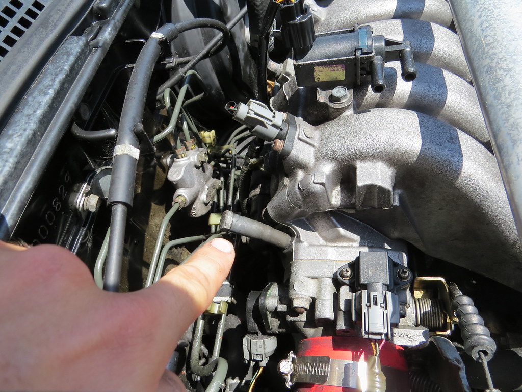
Tubing that has the bolt smashed into it? Does it go to the charcoal canister? There's a mystery tube down under the battery that comes from the canister that has been cut as well.
I'm still not 100% what the top sensor is that has two open nipples but I'm fairly certain certain that it runs coolant through here for the winter time operation. (name of it?)
I looked this up at one point but all of the information is slipping my mind currently. I believe that the FITV below the throttle body has a coolant line run to it as well. but I'm not sure of the routing. There is a nipple off of the exhaust side of the motor, that is on the top side radiator hose (pictured below). It has been blocked off as well. I think that it is the feed line for the FITV and unknown sensor?
I found a guy locally who has a GSR and I'm going to look at his setup and go off of it for parts of this solution.
Tamboo supplied this link to a manual Link
And I found this schematic that will be also used for the routing of vacuum lines Link
This is the schematic for the routing of the coolant lines Link. I've read in a few places that the routing of coolant to these places are only for super cold starts. and since I'm in Florida, we rarely see the temps those are designed for. I'm going to review this information and inform myself of that for sure. But now I have the route paths I was looking for.
Thanks in advance to anyone that can help out.
Since not everyone reads through build threads in their entirety any problems that I post in mine might go un-noticed. Since I'm restoring this '98 GSR. I know that I'm going to run into some stuff that I don't know right away, and in place of making multiple threads about multiple issues, I'm making a catch all thread that will document the problems and their solutions.. Some of it will be my noting issues that I have yet to look up, but will, and some stuff that has me dead in the water. I plan for the list to grow with the thread (hopefully not too large), keep the main problems in this post and fill in the solutions as they come. I know I'm long winded, I'd prefer to give more info than necessary than leave any lacking. Just hang in there with me.
So if you see this thread in the recent activity check in and help a brother out on what ever is stumping me.
Here's the GSR's main thread for anyone who is interested:
http://www.clubintegra.com/board/showthread.php?t=91790
Unsolved issues:
ECU access
Routing of coolant lines to/from sensors
Explanations:
ECU access
The car has been converted to OBD1 via jumper cable. The PO told me that the car was a chipped P72. I read around the internet to see if disconnecting the battery would lose a tune on a chipped ECU to find that cutting power would have no ill effects. Before cutting the power I checked the CEL light to find that it was not on. After giving it power again today and starting/idling it I have a CEL. I tried the jump method on the plug in passenger's kick only to get a slow on/off pattern from the CEL. Which if I'm not mistaken means an ECU error. I'm not sure of the internal work on the engine so I'd hate to put back in a Factory ECU and fry the motor. Assuming that I can't get an OBD scanner to read the ECU, which I have a good feeling that I won't be able to. What should be my next option to figure out the code? My first idea was to open the ECU and see what was going on in there, but as far a tuning like this goes I'm in the dark.
Addition
I used an OBD reader today in a feeble attempt to connect to the ECU. It didn't work as I suspected. Either the jumper harness or the "chipped" ecu caused the problem. I opened the case up and took some photos of each side.
 IMG_2346 by themiller13, on Flickr
 IMG_2990 by themiller13, on Flickr
I don't really know what I'm looking at here. Help me out here. This is only supposed to be a temporary solution until I get a legit tuning system to install.
Routing of coolant to sensors
The PO has cut and dead-ended a some small coolant lines and breather tubes. I want to get everything back to close-to-stock operating order.
Going to start here and work around the engine bay as time progresses.
Tubing that has the bolt smashed into it? Does it go to the charcoal canister? There's a mystery tube down under the battery that comes from the canister that has been cut as well.
I'm still not 100% what the top sensor is that has two open nipples but I'm fairly certain certain that it runs coolant through here for the winter time operation. (name of it?)
I looked this up at one point but all of the information is slipping my mind currently. I believe that the FITV below the throttle body has a coolant line run to it as well. but I'm not sure of the routing. There is a nipple off of the exhaust side of the motor, that is on the top side radiator hose (pictured below). It has been blocked off as well. I think that it is the feed line for the FITV and unknown sensor?

I found a guy locally who has a GSR and I'm going to look at his setup and go off of it for parts of this solution.
Tamboo supplied this link to a manual Link
And I found this schematic that will be also used for the routing of vacuum lines Link
This is the schematic for the routing of the coolant lines Link. I've read in a few places that the routing of coolant to these places are only for super cold starts. and since I'm in Florida, we rarely see the temps those are designed for. I'm going to review this information and inform myself of that for sure. But now I have the route paths I was looking for.
Thanks in advance to anyone that can help out.
Last edited:


