gsr_nikhil
Member
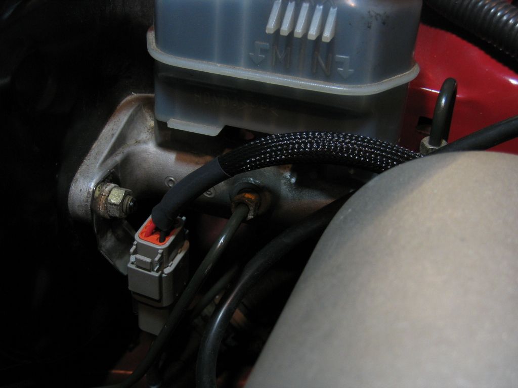
Yes. The bottom one


Really nice :thumbs up
Great question. Short answer, No.Do you run into any issues converting back to obd2 for inspection as far as fuel is concerned seeing as how you have a high compression ration?
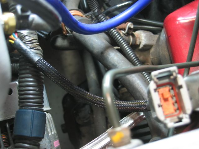
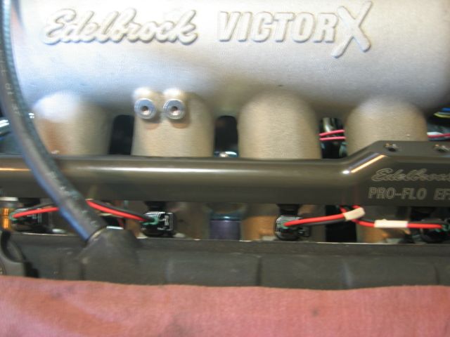
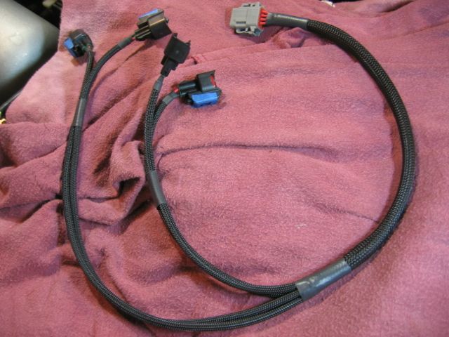
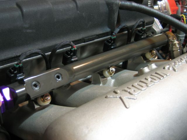
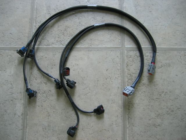
The mesh is great, its flexible, easy to work with and looks professional. Electrical tape is for amateurs.I though about using that mesh stuff to tidy up my bay, I use it all the time when building gaming pc's.
That's good to know!Great question. Short answer, No.
Long answer, the compression (and displacement really) don’t impact the tune as much as you'd think. The reason is we're not putting any load on the engine, this is all part throttle driving, real gentle stuff. Part throttle/low load has a very large margin of tolerance when it comes to AFR and timing.
Actually I pass inspection with all the turbo hardware still installed and the guys at the shop wonder how the hell that’s possible. Simple - "I’m not boosting dummies. Now pass my car!" Just stay light on the throttle, out of boost and everything is fine.
Actually what really gives me the most trouble is the big cams that I am running because they pull low vac at idle and lope quite a bit. To achieve a stable idle at 900rpm I have timing advanced to 18* and the AFR richened up. But the stock Ecu obviously wants to run stoich and 16* at idle which isn’t conducive to these cams. So I prop up the idle rpm by opening the idle screw. The engine will idle at ~1200 rpm so it's less likely to stall. It’s cheating but it works for the brief time its running on the stock Ecu.
I also have to flush the fuel from E85 to gasoline which is the biggest PITA. I tried to run E85 on the stock ECU/injectors before by cranking the piss out of the fuel pressure to compensate for the lack of injector pulse. I actually got it to drive reasonably OK at 90psi base pressure but my Oxygen and catalyst readiness monitors would never set, even after 50 miles. I can only assume EGTs never got hot enough with Eth for them to trigger. Once I ran gasoline, they set within a mile.
The mesh is great, its flexible, easy to work with and looks professional. Electrical tape is for amateurs.
Couldn't have said it better myself :thumbs upThe mesh is great, its flexible, easy to work with and looks professional. Electrical tape is for amateurs.